With the development of technologies such as radars, radios, televisions and mobile phones, the use of electromagnetic radiation exponentially increased, and, in our cities, transmitting antennas for the reproduction of such signals are everywhere.
This rapid growth of these issues produced a substantial increase in the electromagnetic radiation to which we are all subjected, necessitating the implementation of oversight policies to evaluate the electromagnetic pollution and to monitor the quality of individual signals and their coverage.
On July, 1st 2016, the EU states have implemented through national laws, the European Directive 2013/35/EU, which establishes minimum health and safety requirements of the electromagnetic fields exposure for workers.
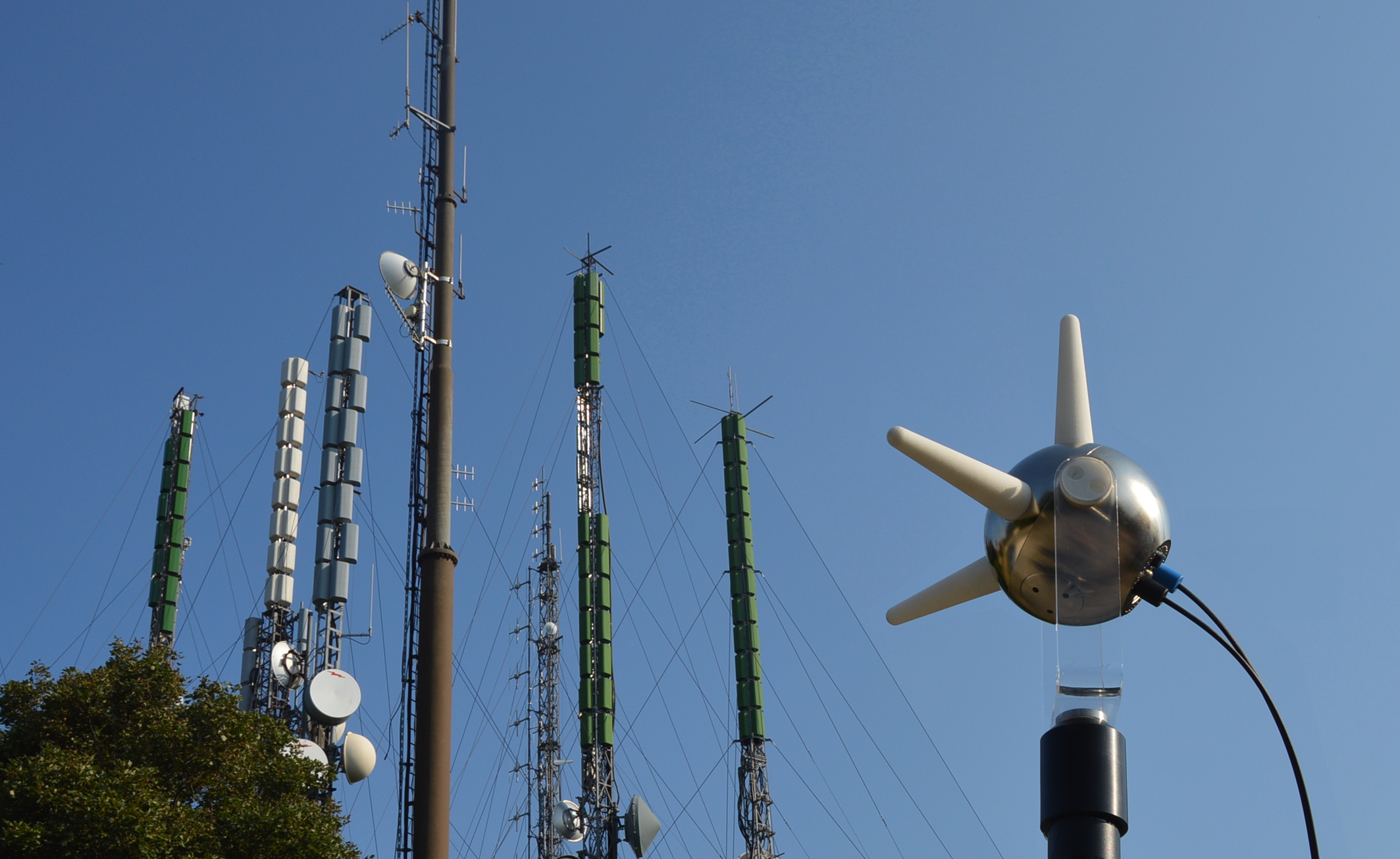
For this reason, and for reasons that drive us to design increasingly high performances and up to date instrumentation, the R&D department at MPB has developed the world's first "all in one" system, capable of containing in only 7 cm of diameter the electronics to selectively analyze the signal (spectrum analyzer), the power supply circuit made with high power lithium batteries, rechargeable and replaceable by the operator, and last but not least, three orthogonal dipoles for the isotropic measurement of the signal .
The table shows the main differences between a traditional measurement system (consisting of an isotropic triaxial antenna, coaxial cable ferrite, spectrum analyzer) and the SEP.
| EXISTING PROBLEMS | TRADITIONAL MEASUREMENT SYSTEMS | SEP (Selective Electric Probe) |
| Use of the coaxial ferrite cable. | The electrical connection between the antenna and the spectrum analyzer goes to interfere on the antenna response in frequency. The errors are not really quantified. The problem cannot be solved but can only be reduced using ferrites. Their use is not optimal in the entire frequency band of the antenna. | There is no coaxial ferrite cable, so there is no problem |
| Isotropy error | Among the three dipoles and the "N" connector there are more cables (RF cable and switching / power cord). All this worsens the antenna isotropy. | The three dipoles are directly connected to the receiver. This design choice was made to minimize the isotropy error. |
| Power supply | Low operation of the battery-powered spectrum analyzer. In many cases, they are not replaceable by the operator. Their replacement implies having to turn the instrument off | Rechargeable and replaceable batteries by the operator without having to turn the instrument off. Long operations |
| Calibration | 3 elements of the system to calibrate: Antenna, Cable and ferrite spectrum analyzer | only the SEP to calibrate |
| Portability and lightness | weight and dimensions are not negligible. Antenna, cable and spectrum analyzer | All in 370 grams |
Other, unique SEP features
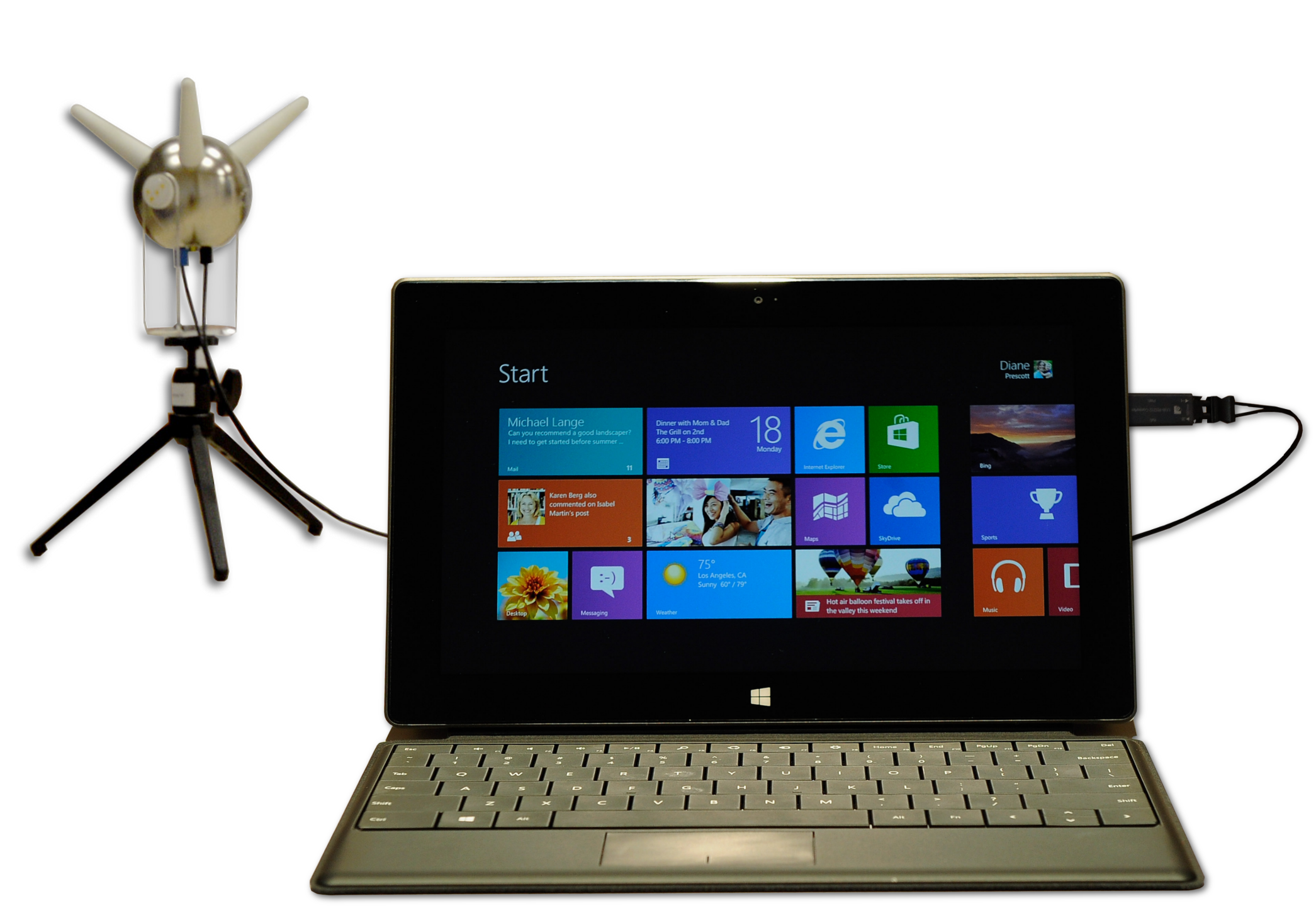
- Connection between sensor and PC is via fiber optic, for managing the measures and saving the data
- The connection between the sensor and the PC is via optic fiber, they will thus prevent any distortion or reflection in the data transfer
- Over 9 hours operation (using 4 batteries)
More technical information can be found in the datasheet.